Case Study as part of a Web-based
Technical and Regulatory Guidance
Red Oaks,
Latimer, Oklahoma
1. Site Information
1.1 Contacts
Dr. Robert W. Nairn
The University of Oklahoma
School of Civil Engineering and Environmental Science
202 West Boyd Street, Room 334
Norman, OK 73019
Telephone: (405) 325-3354
E-mail: [email protected]
1.2 Name, Location, and Description
The project site was the abandoned Bache and Denman underground coal mine
acid mine discharge (AMD). Mining operations occurred from approximately
1907 to at least 1925. The mine is located in the Interior Province, Western
Region Coal Field, in the Howe-Wilburton Coal District (Figure 1-1). The
slope mine occupied approximately 47 acres and was mined using room-and-pillar
methods. Since the stoppage of mining operations and the abandonment of the
mine, AMD began to flow artesian through what is apparently a remnant sump
room discharge pipe. AMD stripped approximately 1 acre of pasture land as
the water flowed downgradient to Oak Ridge Creek, a primary, intermittent
stream. Oak Ridge Creek is a tributary to Red Oak Creek, a seasonally interrupted
third-order stream which flows to the Fourche Maline.
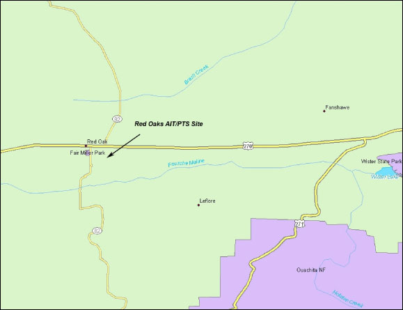
Figure 1-1. Red Oaks alkaline injection technology/passive treatment system, Red Oaks, Oklahoma. Latitude N 34°55'59.4" (34.933167), longitude W 95°2'5.6" (-95.064889); SE1/4, Section 1, Township 5N, Range 21E, Latimer County, OK.)
Created with ArcGIS Desktop Version: 9.3.1
2. Remedial Action and Technologies
2.1 Passive Treatment Systems
This section contains text taken directly from “Design and Monitoring
of a Mine Drainage Passive Treatment System Red Oak, OK,” Robert W. Nairn,
Ph.D., 2004.
Scope designs were developed based on available water quality and quantity data, established contaminant mass retention rates, and project-specific parameters (e.g., available land area, elevation changes, etc.). A five-cell passive treatment system was proposed, designed, and implemented, consisting of an initial oxidation pond and two sets of alternating vertical-flow and surface-flow cells. Flow through the system was designed to be completely dependent on hydraulic head differences. The system was designed to require limited maintenance and operation.
The initial oxidation pond was sized for iron removal from net alkaline mine drainage (the presumed case after CCP injection). The actual cell had approximate nominal depth of 5 ft, 2:1 inside slopes, 3:1 outside slopes, and a total surface area of 0.21 acres. This cell remained unplanted and contained native substrate with no additional material.
The vertical-flow cell design was based on designs successfully implemented at other locations. These cells were designed to both generate alkalinity and sequester metal contaminants. Each vertical-flow cell included three vertical sections. Layer 1 (standing water) provided water head necessary to drive water through the underlying substrate. A maximum of 3-ft vertical elevation (water depth) was provided, plus an additional 1 ft of freeboard. Layer 2 was designed to generate alkalinity via biotic and abiotic means. This section consisted of an approximately 3-ft-thick mixture of organic substrate (i.e., aged horse manure) and high-quality limestone in an approximately 2:1 ratio by volume. Layer 3 was a gravel underdrain (approximately 2 ft thick) designed to act as a highly permeable zone to transmit water leaving the system through a network of drainage pipes. A lower-quality limestone was used to ensure the drainage layer remains intact. Drainage pipe (SDR35) was included in this layer and connected to Schedule 40 PVC risers, which transmitted water to the next cell. The drainage layer was then overlain by the organic matter and limestone mixture. All slopes were 2:1 inside and 3:1 outside. Surface area of the first vertical-flow cell (cell 2) was 0.19 acres, and that of the second vertical-flow cell (cell 4) was 0.15 acres.
Each of the vertical-flow cells included horizontal flush lines from the drainage layer designed to be used only during periods of limited maintenance when removal of accumulated solids from the second layer of the vertical-flow cells was deemed to be necessary. The flush lines were set at the approximate elevation of the drainage layer and discharged to the last treatment cell of the system. The flush lines were designed to remain closed during system operation by placement of slide-gate valves downgradient of the vertical-flow cell but upgradient of cell 5.
The surface-flow cells (cells 3 and 5) were excavated to design depth and received no substrate. These cells were designed to reaerate the waters leaving the vertical-flow cells and further oxidatively remove metals from solution. All slopes were 2:1 inside and 3:1 outside. Surface areas of cells 3 and 5 were 0.11 and 0.10 acres, respectively.
2.2 Alkaline Injection TechnologyThe treatment strategy was designed to create a highly alkaline buffering zone inside the mine by introducing the fluidized-bed combustion (FBC) ash at strategic locations. Conceptually, a buffered region would treat the acidic mine water prior to its discharge and result in lessened surface environment impacts. Once injected into the system, the FBC ash would neutralize existing acid, increase the pH, and impart alkalinity. With elevated pH levels, metal species would precipitate inside the mine as hydroxides and carbonates, among other compounds. The goal was to introduce enough alkaline material to affect the mine system for an extended period of time—what the duration would be was unknown.
3. Performance
3.1 Passive Treatment Systems
This section contains
text taken directly from Porter and Nairn (2008).
Productivity varied among different treatment cells. Nutrient cycling was very rapid to conservative, and macroinvertebrate community diversity, evenness, and trophic structure were relatively high at different sampling locations. The RAPS considered in this study could be defined as an ecosystem in early successional stages based on metrics presented by Odum. Trends in destructive oscillations were observed, and continued discharge of low-oxygenated, high-phosphate water into the later cell will prohibit a trend toward homeostasis. The data collected in this study are not typical of all reducing and alkalinity-producing systems. The presence of more toxic metals and acidic effluents would likely decrease the quality of the communities within the primary treatment cells. Improvements in water quality within the final cells would produce more diverse communities and contribute to more quality ecosystem functions. More extensive research is needed to construct a more defined understanding of ecosystem functions within created ecosystems, specifically RAPS designed to remediate AMD.
3.2 Alkaline Injection TechnologyThis section contains text taken from Winfrey, Canty, and Nairn (2008).
The ~2500 tons of FBC ash injected into the mine was effective at treating the associated acid mine drainage for 63 months prior to June 2007. Alkaline constituents in the FBC ash altered the mine aquatic chemistry in such a manner that existing acid was neutralized, pH was increased (4.75 to 6.6), alkalinity concentrations increased (<PQL to 227 ppm as CaCO3), and metals precipitated. As of June 2007, iron, manganese, and aluminum concentrations were approximately 120 ppm, 5.2 ppm and <0.1 ppm, respectively. With the exception of aluminum, pre-injection metals concentrations were being approached (179 ppm, 6.7 ppm, and 3 ppm, respectively). H2CO3 was increasing as of June 2007 to nearly preinjection levels, signifying the approaching transition of the final treatment phase of this technology. Also, alkalinity appeared to be gradually increasing as the H2CO3 reestablishes equilibrium, while pH was slightly decreasing. Because both of these water quality parameters are changing to a lesser degree than previously observed, it is assumed that treatment Phase 2b was approaching its end. Additional monitoring is needed to evaluate the significance of this transition. Overall, this project has been useful in determining the long-term effectiveness of AIT [alkaline injection technology] as an in situ passive treatment technology for AMD.
In addition, the combination of AIT with other passive treatment technologies is a strategy that has been shown to be effective by this monitoring project. This type of treatment regime could be very useful for abandoned mine reclamation projects that have land available to construct a SAPS [sequential alkaline-producing system].
Table 3-1. Median water quality for the Red Oak Mine discharge
Parameter |
Preinjection (1/95–12/96) |
Post -injection (7/97–12/98) |
pH |
4.4 |
6.3 |
Fe (mg/L) |
200 |
80 |
Al (mg/L) |
6 |
<1 |
Mn (mg/L) |
7 |
4 |
| SO42- (mg/L) |
1021 |
1082 |
Acidity (mg/L as CaCO3 eq.) |
439 |
57 |
Alkalinity (mg/L as CaCO3 eq.) |
0 |
114 |
Ca (mg/L) |
63 |
289 |
Mg (mg/L) |
40 |
33 |
Table 3-2. Mean empirically derived contaminant removal rates for
passive treatment systems
Removal (g per m2 per
day) |
|
| Iron in alkaline waters | 20 |
| Manganese in alkaline waters | 1 |
| Acidity in acid waters in surface-flow cells | 7 |
| Acidity in acid waters in vertical-flow cells | 30 |
| Acidity in acid waters in vertical-flow cells at 40 Gowendemonstration project | 50 |
Table 3-3. Calculated and actual design and sizing needs for Red
Oak passive treatment system
assuming a hydrologic discharge rate of 20 gpm
Targeted parameter |
Concentration (mg/L) |
Loading (g/day) |
Design removal (g • m-2 • day-1) |
Calculated area (acres) |
Actual area (ares) |
Number of cells |
Fe |
200 |
21,802 |
20 |
0.27 |
0.21 |
1 |
Acidity |
450 |
49,054 |
30 |
0.40 |
0.33 |
2 |
Mn (and oxygen) |
7 |
763 |
1 |
0.19 |
0.22 |
2 |
Totals |
0.86 |
0.76 |
5 |
|||
4. Costs
No information is available.
5. Regulatory Challenges
No regulatory issues were encountered.
6. Stakeholder Challenges
There were no significant public or stakeholder issues associated with the
project.
7. Other Challenges and Lessons Learned
Learning to work with private landowners was critical. There was also a need
to demonstrate how it would benefit them.
8. References
Canty, G. A., and J. Everett. 2004. “The Use of
Coal-Combustion By-Products for In Situ Treatment of Acid Mine Drainage,”
presented at the Annual Meeting of the American Society for Surface Mining
and Reclamation, Lexington, Ky.
Porter, C. M., and R. W. Nairn. 2008. “Ecosystem Functions within a Mine Drainage Passive Treatment System,” Ecological Engineering 32(4): 337–48.
Winfrey, B. K., G. A. Canty, and R. W. Nairn. 2008. Evaluation of Coal Combustion By-Products for In Situ Treatment of Acid Mine Drainage. Final report prepared for Combustion By-Product Recycling Consortium Project # 05-CBRC-W03.