5. Construction
BCR performance depends on the care exercised during construction. Much of the construction is accomplished using heavy equipment, often in areas with poor or limited access, and by workers who may be more accustomed to less stringent design parameters. This chapter discusses the construction quality assurance (CQA) necessary during BCR system construction. Construction specifications, developed during the design phase of the project (Section 4.6) describe acceptable products and material specifications, alternatives, performance criteria and schedules to be followed by the construction contractors and confirmed by the site construction engineer.
Following the discussion of CQA are description of the construction features at a site using a BCR to treat MIW. These features include the following:
- the physical setting of the BCR systems (Section 5.2.1)
- typical BCR construction elements including site preparation (Section 5.2.2.1), liners (Section 5.2.2.2), process piping (Section 5.2.2.3),substrateEither (a) a chemical which reacts or (b) a solid surface or (c) an electron donor. installation (Section 5.2.2.4), cover installation when necessary (Section 5.2.2.5), and effluent control (Section 5.2.2.6)
- system performance and monitoring equipment
- site construction restoration
- site security
As a reminder, health and safety requirements during construction, operation and maintenance of BCR systems include those typical of remote construction projects that are also regulated by Occupational Safety and Health Administration (OSHA) and the Federal Mine Safety and Health Act, administered by the Mine Safety and Health Administration (MSHA), as applicable. In many instances training on excavation activities, confined space entry procedures, work with heavy machinery, power tools, uneven terrain, power tools, and work at and near contaminated sites can require 40-Hour Hazardous Waste Operations (OSHAOccupational Safety and Health Administration HAZWOPER) training for those workers that perform activities that expose or potentially expose them to hazardous substances during construction as well as during the treatment of hazardous substances.
Other regulations may apply to the siting of BCRs, including the Endangered Species Act of 1973 which protects the habitats of endangered species. On other sites artifacts or structures with cultural or historic value may be protected by The National Historic Preservation Act of 1966. In addition construction permits may be required from tribal, state, or local authorities. Please consult federal, tribal, state, and local requirements prior to construction.
5.1 Construction Quality Assurance (CQA) Plan
A Construction Quality Assurance Plan (CQA Plan) describes the construction quality assurance procedures in use during the BCR system construction activities. This plan is a recommended project submittal for the BCR based on the design requirements.
The CQA Plan addresses construction quality assurance procedures that are to be used to independently test and verify that the construction activities meet the intent of the design and conform to the construction specifications and drawings. The CQA Plan may be created by the Engineer as part of the design or by the Constructor as defined by the construction specifications. Example components of a CQA Plan are presented below, along with descriptions of key elements of a CQA Plan including definitions, construction quality control (QC) protocols, design modifications, clarifications, and changes, certification reports, and surveying.
5.1.1 Example Table of Contents for a CQA Plan
Table 5-1 presents an example table of contents for a CQA Plan applicable to construction of a BCR system. This example is not intended to be a definitive list of components of a CQA Plan as site-specific design may require different or alternative components.
5.1.2 Key features of the CQA Plan
5.1.2.1 Definitions
The following sections include example definitions for terms used in a CQA Plan. These definitions might be customized for different projects.
Construction/Project Manager – Referred to as the Construction Manager or Project Manager. This individual is the official representative of the Owner and is responsible for all construction activities, including oversight and direction during construction. The Project Manager is also responsible for coordinating construction and CQA activities for the project. The Project Manager serves as a liaison between all parties involved in the project to ensure that ongoing communications are maintained and that resolution is reached for all CQA issues that arise during construction. Duties for the Construction/Project Manager may include:
- Review construction drawings and project specifications.
- Coordinate with the Engineer / Engineer of Record prior to construction to ensure that the construction drawings and specifications are integrated with the CQA program.
- Administer the construction contracts, including any associated changes that occur during the course of construction.
- Assure that Engineer of Record receives required information for review, change requests and other information to assure completion of certification report.
- Coordination of all construction activities
- Coordination with regulatory agencies
- Coordination and implementation of project Health and Safety Plan
- Scheduling and coordination of construction activities with required CQA testing and activities
Engineer – Also referred to as Design Engineer or Engineer of Record, this individual is responsible for the design and preparation of the construction drawings and specifications. The Engineer should be a registered professional engineer in the state in which the work occurs. The Engineer should have the authority to stop any aspect of the work that is not in compliance with the CQA Plan. Work would then resume once a corrective action has been approved by the Engineer. In the absence of the Engineer from the work site, the duties and responsibilities of the Engineer are delegated to the CQA Monitor(s). The specific responsibilities of the Engineer may include the following:
- Develop the construction drawings and specifications, and CQA Plan.
- Train CQA personnel on CQA requirements and procedures.
- Schedule, review, coordinate, and approve CQA activities to ensure that testing and documentation are complete, accurate, and in accordance with the site-specific design requirements.
- Review the QC operations performed by the Contractors(s).
- Ensure that required CQA testing has been performed in accordance with this CQA Plan as well as the intent of the construction drawings.
- Confirm that test data are accurately recorded, validated, reducedIn chemistry, having gained electrons. Often gaining electrons is accompanied with gaining protons (hydrogen). As an example, when O₂ reacts with H₂, the oxygen is reduced, forming H₂O., summarized, and interpreted.
- Approve specific corrective measures to be implemented during construction when deviations from the design and this CQA Plan occur.
- Follow Project Manager-approved Request for Information (RFI) and change order procedures.
- Develop a project file to maintain and store originals or copies of originals of all CQA data sheets and reports generated during the course of construction and following completion of the project. A complete file of this documentation is also maintained by the CQA Monitor.
- Oversee preparation of the Certification Report at the completion of the project.
- Provide final certification that the BCR system has been constructed in accordance with the construction drawings and specifications, and related project documents.
Construction Contractor– The group(s) responsible for performing the earthwork, construction, revegetation, and other construction activities associated with the BCR system. The Construction Contractor may employ various subcontractors, approved by the Owner and Engineer, for completion of the work.
Construction Quality Assurance Monitor – Also referred to as the Monitor or CQA Monitor, this is the firm or individual responsible for performing the tasks outlined in this plan. The CQA Monitor reports directly to the Engineer. The following may be included in the CQA Monitor’s duties:
- Review and understanding of all construction drawings, Contractor-provided shop drawings, project specifications, and related guidance documents.
- Review any required Contractor submittals and make appropriate recommendations.
- Observation and documentation of sub-grade preparation, compaction, cover material placement, surface water controls construction, planting materials and methods, and other site work activities.
- Ensure that testing equipment used and tests performed are conducted according to project specifications and industry standards.
- Coordinate development of the Record Drawings.
- Perform or observe documentation and reporting of test results as required to Engineer and Project Manager.
- Report to the Engineer any deficiencies that are not corrected to the satisfaction of the CQA Monitor, including design or project specification changes.
Owner – Company or Agency that pays for the work to be completed.
Project Construction Drawings and Specifications – Includes all project-related construction drawings and specifications, including design modifications, specification changes, and Record Drawings.
Quality Control (QC) – Functions performed by the Construction Contractors or supplier to conform to the construction drawings and specifications. The Construction Contractors and its designated consultants should implement QC procedures to monitor construction methods, survey controls and any other controls as needed by the Construction Contractors to meet the project specifications and requirements.
Record Drawings – Record (as-built) Drawings record the dimensions, details, and coordinates of the final grading, surface water controls and other structures after construction is completed. The Record Drawings may show any design or field modifications or changes from the original design Drawings.
5.1.2.2 Construction Quality Control
Construction quality control functions are performed by the QC Monitor(s) during construction. The role of the QC Monitor, who is a representative of the Construction Contractors, is to report to the Construction Contractors and to provide construction support and controls so that the design specifications are achieved. The QC Monitor also must coordinate with the CQA Monitor and Engineer.
The Construction Contractors is responsible for developing the QC methods and procedures that are used in the construction, and ensuring the methods are consistent with the construction drawings and specifications.
The Construction Contractor performs and keeps a record of all visual and physical checks. Visual checks (such as material integrity, seaming, and overlaps) may include photo-documentation as well as observation notes to document performance and compliance with the Drawings and Specifications. Physical checks involve surveys, grade checks, physical measurements (such as for proper overlaps, lift thicknesses, and structure dimensions) or other data collection activities, as required to document compliance. Examples of the primary QC functions and observations include but are not limited to the following:
- clearing
- keeping inventory of equipment, materials and personnel on site
- testing fill support to CQA (and associated QC testing and surveying)
- surveys for grade control and for submittal and review by Engineer to review for conformance with design requirements and tolerances
- QC testing
- excavation, and fill placement for conformance to Drawings
- proportioning and mixing of sulfate reducing bioreactor organic substrate
- application of bacterial inoculum on the BCR unit surface if manure is not used as seed
- installation of pipelines and associated plumbing for burial depth conformance
- installation of electrical components including power, instrumentation, and alarm systems for functionality conformance
- testing of riprap or other fill materials for conformance with gradation and physical property requirements
- surface water survey controls (e.g. channel construction, conformance with gradient and cross-section design tolerances, erosion protection revetment)
- concrete structures, including performing QC testing of concrete in accordance with the specifications
- BCR cover placement and thickness control (grade stakes or pre-and post-survey that account for potential lightweight fill (LWF) settlement)
- plant growth medium preparation and placement
- seedbed preparation and seeding
- installation of wetland plants in the aerobic polishing cell (APC)A shallow pond which allows for aeration and settling of particles, typically following a BCR.
- record surveys
- submittals to the Engineer for review (for instance, shop drawings and RFIrequest for information forms) and inclusion in Certification Report
Prior to installation of any materials, the Construction Contractor should verify that all construction materials meet the required specifications. The Construction Contractor should provide the CQA Monitor and Engineer with the manufacturer’s QA/QCquality assurance/quality control documentation including, at a minimum: a certificate of analysis for each lot of material supplied; a description of the manufacturer’s QC procedures for verifying final product quality; product identification numbers; and results of standard material properties testing verifying that the materials meet minimum material requirements.
Any substitutions for the specified materials should be requested in advance and receive approval from the Owner and Engineer prior to use. Substitutions should meet the minimum requirements for the specified material for approval. The Construction Contractor is responsible for all materials from the point of shipping until the material is placed consistent with the BCR design specifications. The CQA Monitor should visually inspect, inventory and approve all materials upon delivery.
The Construction Contractor should assist the Engineer and the CQA Monitor with the test fills to attain the required method specifications for compaction. The test fills QC requires survey control per standard Proctor (ASTMAmerican Society of Testing and Materials D-698) compaction testing.
5.1.2.3 Design Modifications, Clarifications, and Changes
During construction, the need to document design and/or specification clarifications, modifications, and/or changes may arise. In such cases, the CQA Monitor should notify the Construction Manager and the Engineer of the need for any clarifications, modifications, or changes. This notification usually takes the form of a written agreement with documentation by the Engineer and acknowledgment by the Construction Manager. All design deficiencies and construction problems should be documented as well as any design modifications that resolve the issue. Documentation should generally include but not be limited to:
- detailed description of the problem or deficiency including location, cause, how, and when the deficiency was identified
- how the situation or deficiency was resolved
- any measures taken to prevent similar problems in the future
- signature of the CQA Monitor, Construction Manager, Construction Contractor, and certification by the Engineer
- P.E. certification by Engineer for any design changes
5.1.2.4 Certification Report
At the completion of the project, the Engineer should submit a Certification Report to the Project Manager and the Owner. This report certifies that the construction work was completed in compliance with the construction and shop drawings, project specifications, and related documents and be stamped by a registered (state) Professional Engineer. The report should include but not be limited to:
- summaries of all construction activities
- observation and test data sheets
- sampling locations, tests performed, and test results
- description of any significant construction problems and/or design deficiencies and how they were resolved
- copies of any design and/or specification clarification, modification or change forms
- documentation submitted by the CQA Monitor (daily construction reports, weekly progress reports, pictures, and field test results)
- record (as-built) drawings that accurately locate all site work such as construction items, erosion control systems, dimensions, and cover thickness
5.1.2.5 Surveying
Record survey documentation should be conducted as part of the Construction Contractor’s QC, with the CQA Monitor conducting periodic spot reviews and checks. The use of a Global Positioning System (GPS) receiver calibrated to the local site GPS network using site coordinates can assist in this documentation.
5.2 BCR Construction
5.2.1 Physical Settings
5.2.1.1 Siting the BCR System
Most passive treatment systems are located in remote, hard to access areas close to the source of MIW to treat. In some instances the mining-influenced water is captured and conveyed, piped, or pumped to the BCR system, which may be some distance from the MIW source.
Although the design of the BCR already considers numerous site-specific construction factors, finalizing the protocols, timing and procedures to bring construction equipment, materials and personnel to the BCR construction site is recommended. Constructing the BCR system during the early spring sometimes is recommended to avoid unnecessary vegetation clearing and avoid construction during rainy and winter seasons. Commissioning of BCR systems during the summer and fall are recommended. The local vegetation of the area takes a significant role where the influent water is routed to a convergence point because the plants can increase the dissolved oxygen (DO) of the MIW and may cause some metals to precipitate.
5.2.1.2 Water Influent Control System Installation
The simplest BCR water influent conveyance is the one that occurs naturally as a single stream that connects the MIW to the BCR system. The construction phase may call for increasing the stream side banks to match a specific maximum design flow that the BCR can support and channeling the water flow to the BCR influent structure. During intense precipitation events the maximum design flow may be surpassed and by-pass or diversion channels need to be constructed to relieve the excess flow to the BCR system. It is common to construct an influent bypass during construction and/or in high flow conditions. A by-pass box can be designed such that the excess overflow is diverted hydraulically using an overflow weir to the by-pass system.
In many cases the design includes an influent control structure (see Section 4.4.2.1). The Construction Contractor determines the construction methods for this structure, including the method applied to bypass MIW from the site during the construction process.
In other cases, the capture and conveyance of the MIW influent requires the design and construction of permanent structures such as spillways, or underground piping that connect the influent flow to the BCR system. Figure 5-1 show one example influent structure that required the use of an underground concrete piping that directs the influent to the headA specific measurement of water pressure above a geodetic datum. It is usually measured as a water surface elevation expressed in units of length. of the BCR system.

Figure 5-1. Example of influent structure on a BCR.
The presence of sediment, either in the MIW influent or resulting from the BCR construction phase, can negatively affect the performance of the BCR and must be managed and controlled using temporary or permanent settling basins or sediment traps.
In addition to MIW local regulations, tribal, state, and federal regulations may apply to storm water management at the site during construction. Stormwater management during construction of the BCR can be as simple as inspecting the stormwater drainage area or basin to ensure that minimum stormwater flows are allowed to the BCR system. In other cases, major stormwater drainage basin modifications would be needed and called for in the design. Implementing these changes may require close coordination with local and state watershed basin stakeholders. Some of the stormwater management practices that are implemented during construction, specifically those aimed at managing soil erosion and controlling the disturbance of sediment and siltation, are also implemented during operation of the BCRs.
5.2.2 BCR Typical Construction
This section presents guidance on typical construction aspects of a BCR unit, including site preparation, liner installation, process piping installation, substrate installation, and cover installation. Although the overall treatment system may consist of the BCR unit, influent and effluent components, and pre- and post- treatment components, this section focuses on construction of the BCR unit component, and also presents general discussion of the relation of the BCR unit construction to other components of the overall treatment system.
5.2.2.1 BCR Site Preparation
Construction of a BCR system begins with preparing the site area. The site preparation task for the BCR unit includes, but is not limited to:
- road access improvements and physical hazard markings
- development of staging and temporary facilities
- development of erosion control and storm water runoff features
- clear and grubTo remove plants by digging up the roots and/or stumps. of trees, stumps, and brush
- earthwork preparation of the BCR unit base and other related components
- management of excavated and cleared and grubbed materials
Abandoned or active mine sites often have disturbed land areas in which the BCR can be constructed. In this case, minimal clear and grub activities may be required. Many mines are also located in steep or sloping terrain. In these cases, areas must be excavated and re-graded according to the design. In remote areas, road construction may be required as the first scope of work in order to provide access to the site. Additionally, areas disturbed by mining activities may be contaminated by metals or other constituents. If contaminated materials are present, excavated materials must be handled in accordance with the design or other site requirements, such as disposal in an on-site repository or off-site location.
BCR units can be in-ground or above-ground, depending on site conditions. For in-ground units, the unit area is excavated according to the construction plans, and overburdenGeological term for the material above solid rock. Sometimes called "soil". (soil) material may be stockpiled for construction of other components of the overall treatment system. Above-ground units require borrow from a stockpile of overburden already present on site, developed from a nearby area, or brought in from off site in order to construct the unit berm. Some BCR units may also be partially in-ground, where the excavated overburden is used to build a berm on the sides of the unit, thereby extending the overall depth of the unit. It is also possible that a BCR unit is constructed within an area of bedrock, in which case bedrock must be blasted and removed to create the depression necessary for the unit installation.
If deemed acceptable in accordance with the design, excavated overburden material could also be used for construction of several other components such as run-on/run-off control features (such as berms or drainage channels), riprap, influent/effluent channels, pond berms, roads and other access features, growth media for vegetation and erosion control, and cover material for the BCR unit. Importing off-site material for construction may also be required for these various components. Re-use of excavated overburden or other local on-site resources is an important component of the project, as this can reduce overall cost of hauling materials. Since these various uses may require different particle size gradations and/or other soil/rock properties, overburden may need to be screened, separated, and amended in accordance with the design. There is also potential to chip or shred the cleared and grubbed woody vegetation material and incorporate it into the BCR unit substrate, if this material is deemed appropriate as prescribed by the design.
The design determines what site preparation procedures are to be followed. Construction QA/QCquality assurance/quality control procedures must be adhered to during site preparation to ensure the BCR unit size, depth, and grades meet the design requirements, which are critical components for successful operation of gravity fed systems. Surveying should be conducted prior to, during, and after unit construction to ensure the line grades are met. The elevations of the influent, effluent, overflow, and other features must meet the design requirements in order to reduce risk of future potential issues with improper loadingMass of something per time entering a volume (volumetric loading rate) or flowing into an area (areal loading rate). to the system. Issues that could result from poor construction grading could include overloading the system beyond the designed limits and allowing the system to become dried out. These system stresses can lead to issues such as reduction in treatment efficiency, loss of appropriate bacterial community, and plugging as further discussed in Section 4.
Another element of site preparation construction is implementation of proper erosion control practices. As common for earthwork construction, materials such as silt fences, diversion channels and ditches, sediment capture ponds, and similar features may be required. The main purposes of utilizing erosion control practices are to prevent damage to downstream resources, limit loss of material stockpiles or other features as a result of stormwater erosion, and to route stormwater around construction areas to improve the safety of work conditions. For the BCR unit, it is also important to have a storm water diversion and dewatering plan in place in the case of high precipitation events occur during construction. Proper implementation of these features is typically required prior to all land disturbance. An erosion control plan and/or storm water pollution prevention plan should be developed and implemented that defines the approaches for erosion controls.
Since the intent of the BCR system is to treat MIW, an actively flowing source of MIW may be present near the BCR construction area. This MIW should be managed accordingly to prevent it from entering the work area and prevent contamination of otherwise clean soil or granular fill resources used for construction. MIW should be routed around the work area, treated, or stored in a containment pond as required per the design, mine operating plan, or other requirements.
5.2.2.2 Liner Installation
The base or floor of the BCR unit may be constructed in a number of different ways depending on site conditions. In the majority of cases, a liner is specified to prevent seepage of surrounding groundwater into the BCR unit or leakage of MIW from the BCR unit. In the case that the BCR unit is constructed within native clay or similar low-permeability soil, a liner may not be required. However, adequate testing of the soil conditions should be conducted to ensure that the BCR unit holds water.
A liner system can be constructed of a number of different materials that are common for dam, pond, or impoundment construction (see Appendix B.13 Copper Basin Mine Case Study). These material types may include PVC, high density polyethylene (HDPE), linear low density polyethylene (LLDPE), and geosynthetic clay liner (GCL). For more information on liner components see
- inspection of liner material for defects
- documentation of sheet material properties and testing to meet the design requirements
- evaluation of proper liner bedding material to prevent liner damage or puncture
- field trial seam development and testing to determine if the field welding process creates seams that meet the design requirements for material properties
- destructive and/or nondestructive field seam testing ensure the continuity and integrity of in-place field seams
For some materials, the liner can be manufactured as one continuous piece. In this ideal situation, field welding of sections would not be required, thereby reducing the amount of construction cost associated with welding and testing. The only field welding that may be required in this case is for pipe penetrations for the influent and/or effluent piping.
After completion of the of the site preparation for the BCR unit, the liner bedding is installed. The bedding material is typically a non-angular sand or fine gravel so as to not damage the liner. Due to the specific particle size and shape requirements for bedding material, it may be imported from an off-site location that has the appropriate processing equipment. Alternatively, on-site resources may be present and could be used. As described for site preparation, use of on-site materials for bedding can help reduce costs. The bedding layer is placed according to the thickness defined by the design (typically 3 to 6 inches) and compacted. The bedding surface should be smooth and free of rocks or other protrusions that can damage the liner. Inspection of the bedding should occur prior to liner installation to ensure the design conditions are met.
The liner is installed after placement and inspection of bedding. Liner installation can proceed by first anchoring one side of the liner sheet into the pond berm, and rolling the sheet across the BCR unit base. The liner may also be laid out over the BCR unit with excess liner temporarily anchored until field welding is completed. Ultimately, the method of liner installation should be per the manufacturers’ and experienced installers’ recommendations. Final anchoring of the liner on all sides of the BCR unit is conducted by excavating a shallow trench (typically 1 to 2 feet deep and up to 1-foot wide), laying the liner along the walls and floor of the trench, and backfilling and compacting soil into the trench. Backfilled trench materials in direct contact with the liner should meet the same typical requirements as for liner bedding.
Field seaming of sheets is conducted in accordance with the design and manufacturers recommendations and should be conducted by qualified personnel. Penetrations through the liner for influent and/or effluent piping may be required. A pipe penetration is installed by cutting the proper size hole in the installed liner, feeding pipe through the penetration, welding a piece of liner material to the sheet around the pipe, and clamping the liner around the pipe to create a seal.
The last component of liner installation is field seam testing of sheets and pipe penetrations to ensure that leakages do not occur and to test the properties of a field seam. Field seam testing can be conducted using destructive or non-destructive methods, depending on the type of material installed, extent of field seaming, and field conditions. Destructive field seam testing involves collecting a sample of the seamed area and submitting to the laboratory for testing. Non-destructive field seam testing involves either vacuum testing (pulls a vacuum on a seemed area) or air pressure testing (inserts air into the enclosed space between a double-track fusion seam). The type of testing method to be used is dependent on the type of liner material and type of field seaming method. Based on the results of field seam testing, repairs to seams may be required, and the area should be re-tested upon completion of the repairs.
5.2.2.3 Process Piping Installation
Process piping for BCR systems includes influent and effluent piping outside of the BCR unit, and piping within the BCR unit. As for site preparation tasks, it is critical to install process piping to meet the grading, pipe material type, and pipe connection requirements prescribed by the design. These elements are critical to success of a long-term functioning system. Typical process piping material for BCR systems are PVC, smooth-walled HDPEhigh density polyethylene and corrugated HDPE. Within the BCR unit, PVC or corrugated HDPEhigh density polyethylene piping is most common because of lower price and ease of installation. Effluent collection piping for a downflow BCR unit is also typically perforated. Effluent for an upflow BCR unit may not require effluent piping, rather the system is graded to drain by overflow at the top of the unit although during high flow conditions the potential for short-circuiting at the BCR may be observed if not designed properly.
For downflow BCR units, effluent piping is installed at the bottom of the unit. Pipe bedding is first installed over the liner to aid in achieving proper grade. Pipe bedding in direct contact with the liner system should be similar to the bedding used for liner installation to prevent liner puncture. Bedding directly around the perforated pipe is commonly a poorly graded gravel to aid in drainage. This material may also be limestone gravel, which can add additional alkalinity to the effluent. Gravel or any other backfill placed over piping should be conducted carefully to prevent damage to the piping system. The depth of gravel over top of the effluent piping should be placed in accordance with the design and confirmed in the field prior to additional backfill of substrate into the BCR unit.
The effluent piping can be configured in a number of ways. For example a gallery of perforated effluent piping may be installed. This consists of several lines of perforated pipe in parallel which are connected a main effluent header that feeds to the effluent pipe through the liner penetration. Assuming the effluent pipe through the liner is installed near the bottom of the BCR unit, effluent piping installation should continue from this point outward, or the gallery should be constructed, graded, and connected to the effluent pipe. All piping, couplings, elbows, and other fittings should be inspected for defects prior to installation. The effluent system may also contain more than one effluent pipe gallery in parallel. In either case, grade checks should be conducted throughout effluent pipe installation to ensure grades are met. All inspections of grade should be documented on appropriate forms or in a logbook. Adjustment to grade can be achieved by adding more or less bedding beneath the piping.
For upflow BCR units, influent piping that evenly distributes the flow to the bottom of the system would be installed similarly to that of an effluent collection piping gallery described above for a downflow system. The key difference would be proper pipe grading in the opposite direction of the effluent piping for a downflow system. For an upflow system, the effluent would typically rise to the surface and overflow into discharge channels or other flow control structures such as an overflow spillway.
Some horizontal flow BCRs have been constructed, but are not as common as downflow BCRs. Flow can be delivered to a horizontal flow system along one side of the BCR unit via a series of influent pipes or a perforated pipe gallery that evenly distributes flow. Similarly, effluent would be drained on the opposite end of the unit using a collection gallery. Perforated influent or effluent galleries would be constructed similar to upflow or downflow BCRs, expect that the piping galleries may be raised off of the unit floor. Suspended piping systems may require adequate anchoring and support systems during construction. In other cases, the flow follows a serpentine pattern through multiple reaction units where the influent to one unit enters at the bottom at one corner and the effluent leaves at the opposite corner of a rectangular or square reactor (see Appendix B.10 Peerless Jenny King Site Case Study), as dictated by space availability.
Piping installed outside of the BCR unit also requires bedding material, although the type of bedding is typically a well-graded sand or gravel, or alternatively on-site overburden materials could be used. Trench excavation would be required for buried piping. Bedding is placed within the trench, and then pipe is installed to grade. Backfill is placed over the piping and compaction is completed with caution to not damage the piping. A common practice to install flagging or a warning tape at least six inches above the piping to prevent potential damage if piping ever requires future maintenance. Above ground piping may require anchoring systems, especially on steep slopes.
Valves are not likely within the BCR unit, but may be found at the effluent or influent of the unit in areas that can be accessed for maintenance. Construction of access to valves or other process control equipment may require construction of an in-ground manhole or vault, and require additional safety precautions during operation of the BCR. Installation of these kinds of structures must also occur with close attention to required grades. Proper bedding for structures should be installed, compacted, and tested for density as required. This bedding is critical to reducing potential for future settling of the structure, which could lead to damage to piping entering or exiting the structure. Below ground structures may also be considered confined spaces and adequate procedures should be implemented to ensure the safety of workers during installation and during future operations and maintenance. Sampling ports or automated monitoring devices may also be present within the structure or near the valve area. Connections to valves, or any other device, to process piping should be conducted by qualified personnel to ensure leakage does not occur. Leak testing of connections or the piping system, as a whole may also be required prior to backfill over piping. All testing should be documented on appropriate forms or a log book.
5.2.2.4 Substrate Installation
As discussed in detail in Section 3.1, the substrate for a BCR can include a number of different materials. The substrate in a BCR is the main component by which the MIW is treated. Typical BCRs include solid substrate materials placed in the unit. In some cases, liquid substrates may be added to the influent stream. The types and proportions of materials are developed in the design based on results of the bench and pilot testing that indicate the best treatment approach for the site MIW. As such, the proper proportioning of substrate materials for the full-scale system is vital to the success of the reactor to adequately treat the MIW. If not done during the testing phase, the substrate materials should undergo comprehensive testing for incidental contaminants that could be introduced into the system.
Installation of the BCR substrate begins with understanding the conversion between volumetric and mass quantities of substrate materials. Bench and pilot studies and design parameters may be developed using either one or the other type of quantity, or both. Purchase and hauling of large quantities of substrate materials may also be measured in either unit. Therefore, the conversion between these units (density) is critical to properly proportioning the substrate materials. Additionally, the percent moisture can have a large effect on materials measured by weight. Prior to construction (if not done during the design), samples of substrate materials can be submitted to a laboratory to test the density and percent moisture of the materials (Section 3.2.1). This step may be conducted during the bench or pilot test phases. Alternatively, this information may already be available from the material supplier or determined based on past experience and/or literature values at the discretion of the Engineer and Construction Contractor. The material properties are then used to properly coordinate with the Construction Contractor on how to blend the materials in the field.
Delivery of each of the substrate materials to the site in truckloads should be placed in separate areas prior to field mixing. Upon each delivery, documentation of the contents volume and properties should be provided in accordance with the CQA Plan. Based on the proportioning of materials in the design, mixing batches of substrate can then commence. This procedure should proceed using a method that is simple using standard earthwork construction equipment. One approach is to proportion the designed substrate mix using excavator bucket loads of each material. The size of the bucket is determined and then fractional amounts of each component are grabbed with the excavator and placed in a pile. The pile is then mixed using the excavator bucket, site workers, and/or tilling equipment. Concrete mixers also have been used. Such mixers mix well but have limited batch sizing.
As part of CQA requirements, the Construction Contractor should create a test batch prior to full-scale mixing. The test batch would use the same approach as described above, but at a smaller volume. Development of the test batch should be observed by construction oversight personnel. This observation allows for calibration of the mixing method used that ensures the designed proportions are met. The mixing procedure should be approved by the oversight personnel prior to full-scale implementation.
After installation of the pipe and gravel bedding, the substrate is installed. A geotextile filter material may be required over the gravel layer prior to substrate placement. The geotextile reduces loss of fine-grained substrate material into the gravel layer, while allowing adequate water flow to the effluent drain system; however, the geotextile should not be too fine that in may cause plugging.
Placement of substrate material within the BCR unit can be conducted in a number of ways, but all should be implemented with caution to not significantly compact materials once placed. Significant compaction of substrate material can cause reduction in permeability in certain areas of the BCR unit and result in reduced treatment efficiency and potential plugging issues. In some cases, the design may call for minor compaction to meet a certain permeability requirement; however, the key for substrate placement is to provide uniform compaction throughout the unit. Non-uniform compaction or excessive compaction is some areas can cause preferential flow pathways in less compacted areas and reduction in treatment efficiency.
Substrate materials can be installed from equipment along the outside of the BCR unit, with light-duty equipment within the unit, or a combination of both methods. Placement depends on whether water flow is vertical or horizontal.
Vertical flow BCRs: For installation from the outside of the BCR unit, an excavator is used to place substrate into the BCR unit and spread the material without entering the BCR unit. This process proceeds around the entire perimeter of the unit until all material is placed and leveled to the required depth. This approach reduces the issues regarding compaction of the substrate or damage of collection pipes while the substrate is being installed. However, this method is limited to placement at the reach of the excavator. If the excavator reach is less than the geometric radius of the BCR unit, then proper spreading of the substrate cannot be conducted using the excavator. In this case spreading substrate in the center of the BCR unit must be conducted by small track mounted skid loaders that can enter the BCR. Figure 5-2 shows sketches of vertical flow BCRs.

Figure 5-2. Vertical downflow and upflow BCRs.
If equipment can be operated on the gravel bedding layer above the liner, another method of substrate placement is to dump truckloads periodically spaced throughout the unit. The decision to drive trucks over the gravel bedding (portions of which may contain buried pipe) should be made based on the compaction properties and thickness of the gravel placed over the piping gallery. An entrance ramp to the BCR unit should be constructed with a layer of additional protective material over the liner to prevent damage by heavy construction equipment. A small track mounted skid loader should then be used to spread the substrate piles into a uniform depth. The loader should start at the opposite end of the entrance ramp to the BCR unit and work backwards toward the entrance until the entire BCR unit has been graded to a uniform depth.
Horizontal flow BCRs: As with vertical flow BCRs, an excavator is used to place BCR substrate and alternating rows of gravel, but the unit may be constructed from one end to the other while equipment operates on the non-filled portion of the unit. Figure 5-3 shows a sketch of a horizontal BCR, the upper of which is at the Peerless Jenny King site (see Appendix B.10 Peerless Jenny King Site Case Study) and the lower is an example included in the ADTI Handbook (http://wvwri.nrcce.wvu.edu/programs/adti/pdf/adti_handbook_5.pdf).

Figure 5-3. Cross-sections of horizontal flow BCRs.
The method of constructing the rows of substrate and gravel may not be specified and may be labor intensive. An illustration of one such installation is shown in Figure 5-4.
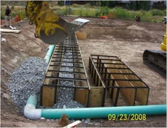
Figure 5-4. Horizontal BCR media placement.
Source: Jeff Schoenbacher Park City Municipal Corporation.
Another alternative for substrate placement regardless of flow direction is construction of a dividing earthen berm between parallel BCR units or sections of a BCR unit. If not in the design drawings, adding berms require the Construction Contractor to obtain concurrence from the Owner and Engineer. The berms provide the benefit of an access route for construction equipment to install substrate and also to perform maintenance on the substrate. The berms can be constructed within the overall lined system. As an example, berms can be constructed that divide a rectangular unit into two or more sections. The berm should be constructed after the liner installation, but prior to or during bedding and effluent pipe installation. The berm height should be equivalent to the BCR unit height at the perimeter of the unit and compacted in lifts as appropriate. In some cases part of the top of the berm is built at a lower elevation to allow for overflow by design or serve as the actual effluent of the BCR. A protective layer of soil should be placed directly over the liner surface prior to placement of other soil materials that may contain angular gravel or other debris that could damage the liner. The segregated areas created by the berms can then be equipped with separate effluent drain systems and appropriate influent/effluent valves. Separating a BCR into units provides opportunity for maintenance of a portion of the system (such as removal of substrate) while the other units continue to treat MIW. Building BCR units in parallel or sections is part of an overall design approach to improve capability and efficiency of maintenance on substrate materials over time. The basis for this approach is discussed further inSection 4.2.5 and maintenance approaches are discussed in Section 6.
5.2.2.5 Cover Installation
As determined by the design, a cover over the substrate layer may be beneficial. This determination is mostly based on climate (Section 2.6). Cold winter climates can have adverse effects to the BCR unit sulfate reductionThe stripping of oxygen atoms from sulfate (SO₄²⁻), most often yielding sulfide (S²⁻) as an ultimate product. rate due to the low temperature. Also, a cover may be desired based on the designers’ preference and experience. Covers can also help with reduction in odor issues caused by hydrogen sulfide gas production from the sulfate reduction reaction.
The cover system can consist of any number of materials, preferably overburden or other on-site materials leftover from the BCR construction to reduce costs. Placement of cover material must also be carefully conducted to limit compaction to the substrate layer. As such, a higher density material such as gravel or rock may not be preferred. Layers of wood chips have been used at a few sites. The placement and grading of cover material should be installed from the perimeter of the system using excavators. If equipment must be driven onto the BCR unit surface, sufficient cover material should be installed first within the area that the equipment operates.
Cover material generally should be sufficiently sloped to shed stormwater off of the BCR unit surface, assuming the cover extends to the top of the BCR’s containing berm. Grade checks should be conducted periodically to ensure the designed cover thickness and grades are met. The cover should also be graded and tied into runoff/run-on diversion structures along the perimeter of the BCR unit, if present. Routing water from the BCR unit surface towards the influent or effluent areas should be avoided. Otherwise, inflow of runoff water into these areas could increase the amount of water to be treated in the BCR or in subsequent posttreatment steps.
The design may consist of a low permeability cover system, which would involve a material similar to the BCR unit liner that limits infiltration. Placement of this kind of cover should be conducted similar to the methods discussed for liners in Section 5.2.2.2, depending on the type of material. The low permeability liner should have a protective layer placed over the liner and may also have a seeded surface. This layer protects the liner from photodegradation and heave/thaw affects that could damage the liner. Ventilation of gases (hydrogen sulfide) within the BCR unit may be a required component of the cover system. If this is required, vent pipes would be installed through the cover system. Penetrations in the liner for the vent pipes should be installed as described for liners installation in Section 5.2.2.3.
5.2.2.6 BCR Systems Effluent Control Installation
Treated effluent from a BCR can leave from a constant elevation overflow pipe via an open or valved piping system, or as an overflow pipe or overflow spillway from the BCR. There are also adjustable water head control valve boxes that allows a predetermined water head in the BCR unit to be maintained. Figures 5-5 and 5-6 present a constant head overflow discharge pipe and an adjustable head overflow device, respectively.

Figure 5-5. Example constant elevation BCR overflow discharge.
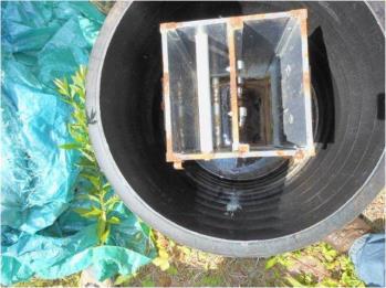
Figure 5-6. Adjustable elevation head weir for BCR effluent.
Mechanical failures from the effluent system include the freezing of the effluent control valve that controls the effluent for the BCR, if present. Although a good valve exercise program minimizes the potential for the valves to become stuck, the presence of solid mineral deposits including iron and other metal hydroxides or sulfides make the BCR effluent valves susceptible to failure. Also, the adjustable weir boxes used in BCR effluent systems are also prone to become stuck due to the presence of mineral build up.
5.2.3 BCR Systems Performance and Monitoring Equipment Installation
The BCR units are constructed with some monitoring wells and piezometers that allow for monitoring the performance of the BCRs as well as the performance of the BCR liner. Figure 5-7 presents a BCR with monitoring wells and piezometers. In addition, there may be monitoring ports within the BCR itself (see Section 4.3.4). These are normally used to ensure that the hydraulics of the BCR are acceptable and that there is no apparent short circuiting of flow as well as providing a location where water samples can be collected within the BCR unit. These monitoring wells can provide information on the performance of the BCR, the location of the anoxic zone, and location where substrate may be compromised.

Figure 5-7. BCR monitoring wells and appurtenances.
In addition, sometimes it is necessary to cut and extract a vertical transect of the BCR to ensure that the various BCR zones are clearly defined in the cross section. This type of sampling is rare but can be extremely useful during the diagnosis of the BCR performance.
Watershed Groups and Treatment Systems
Despite the presence of watershed groups able and willing to operate and maintain treatment systems in hard rock areas of the west, there are few funds to assist them. Presently, CWAClean Water Act Section 319 program funds often cannot be used at these western sites because many of the discharges are considered to be point-source discharges, thereby rendering them ineligible for 319 funding. See Section 8 for more detailed information.
Most MIW BCRs do not contain automatic flow and sampling devices and rely on the manual monitoring performed by experienced personnel, including trained private companies, federal or state personnel as well as local organizations and site stakeholders representatives. The design of the BCRs normally provides sufficient technical information to determine a raw and treated effluent chemical characterization that the samplers are familiar with and compared results such as pH, temperature, ORP, DOdissolved oxygen, and actual water chemistry samples of heavy metals, sulfate, sulfide, alkalinity and other site-specific parameters, as designed (seeSection 6.2.2.2 for a comprehensive list of parameters).
BCR effluent monitoring commonly is comprised of a discharge pipe where effluent sampling using field monitoring equipment such as a stopwatch and bucket for flow determination, pH and ORP meters, and thermometer are used. Samples for off-site analysis can also be collected from the BCR effluent. Figure 5-8 shows a BCR discharge pipe with field equipment being used.

Figure 5-8. BCR effluent monitoring.
Automated monitoring equipment include open channel primary and secondary flow measuring devices as well as automatic samplers that can be programed to collect BCR effluent (and influent) samples based on a predetermined sampling protocol. Section 6 of this guide presents a detailed description of automatic flow monitoring and samplers used for MIW BCRs. The precautions necessary for the installation of primary flow monitoring devices is to provide access and infrastructure for the installation of primary flow monitoring devices, including an open channel and weir system as well as conditioning the site to locate the flow and sampling equipment in a safe, secured and reliable location.
In addition a small wood shed or prefabricated shed is normally useful to keep sampling equipment and consumables needed for flow monitoring and sampling purposes. Sampling equipment may be operated by the use of solar power and solar panels and photocells need to be installed such that direct sunlight is maximized. In addition, sampling devices can be powered by water wheel technology.
5.2.4 BCR Systems Site Construction Restoration
The BCR system design drawings and specifications normally include a section on the site construction restoration that includes the minimum restoration design criteria after the BCR system is built. Site restoration can call for re-establishing the site not occupied by the BCR system to its original state, matching existing conditions to the area surrounding the work site or partially restoring areas, allowing access roads, building, and specific features to remain.
As the site restoration takes place, field QC of restoration activities may require approval by stakeholders, such as the appropriate grass seeding mix needed as well as documentation of restoration activities and meeting site restoration conditions. After topsoil placement and grading is complete, the surface is normally roughened (raked) prior to applying fertilizer and grass seed. The topsoil is loosely compacted to promote growth.
Following placement of the impermeable geo-membrane over the bioreactor, general backfill and topsoil are often placed and loosely compacted with a final grade normally 1-foot above the surrounding grade to allow for surface runoff. Final grade along the perimeter of the BCR Unit can gradually blend into the surrounding surface grade.
All remaining disturbed areas (such as backfilled trenches, monitoring well completions, stockpile areas, haul routes, and support construction areas) may need to be restored to conditions similar to or better than pre-construction conditions. This restoration may include the addition of topsoil, fertilizer, and seeding as required.
Restored areas are normally maintained, protected, and sometimes fenced to limit access to the BCR system site. All restoration activities are normally coordinated with the owner or owner’s representatives to ensure that restored areas are completed to their satisfaction.
5.2.5 Site Security
During BCR system construction, all visitors to the work site are normally required to report to the site construction manager as soon as they arrive on site. The area immediately surrounding the BCR system construction work area is normally marked through the use of signs, barrier rope or tape, or fencing. BCR system security is designed to prevent exposure of unauthorized, unprotected individuals to the work areas.
Due to their generally remote locations, BCR system construction site security can range from nonexistent to chained-linked wire fence, depending on the location of the BCR system and its proximity to urban areas. More sophisticated security systems such as camera and motion detector-based surveillance systems are normally not necessary as part of the BCR system construction, but may be necessary if the BCR system is adjacent to a site that requires surveillance.
Publication Date: November 2013